Analog Input Stage
The signals acquired by the OPX using the analog input channels are first passed through an analog input stage and then digitized. Here we discuss the voltage limits, gain and offset calibrations that can be applied to the signal to be digitized.
Acquiring analog signals with the OPX
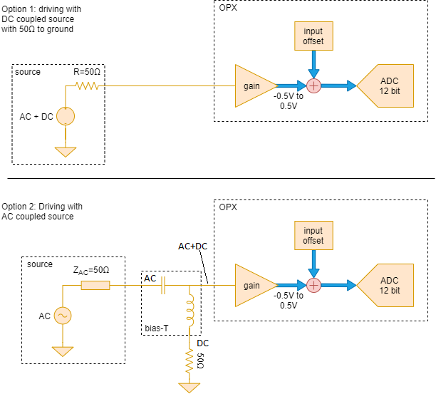
The signal chain can be seen in Fig. 1. The signal source can be either AC or DC coupled.
DC coupled signal source
If the signal source is DC coupled and has 50ohm DC resistance to ground, it can be directly connected to the analog input. This can be seen in Option 1 of Fig. 1
AC coupled signal source
If the signal source is AC coupled and does not have a 50ohm resistance to ground, a bias T is needed in order to bias the input amplifier. The required setup can be seen in option 2 of Fig. 1. In this case, the source will still need to have a 50ohm AC impedance throughout its bandwidth for proper operation.
Properties of the analog input stage
The analog input has the following properties:
Input impedance: 50ohms
ADC resolution: 12 bits
input bandwidth: 400MHz
full voltage range: 1.0Vpp into 50ohm or 4dBm (nominal)
variable gain: -3dB to 3dB in steps of 1dB
Setting the voltage gain
The voltage gain can be set by adding a "gain_db" field to the "analog_inputs" field
of the controller in the config. Here we show an example with the relevant fields:
config = {
    'version': 1,
    'controllers': {
        'con1': {
            'analog_inputs': {
                1: {'offset': 0.0, 'gain_db': -1},
                2: {'offset': 0.0, 'gain_db': 1},
            }
        }
    },
}
Warning
the maximal power that can be input to the ADC without significant distortion is 7dBm or 1.4Vpp. This can be attenuated down by 3dBm to enter the full voltage range of the ADC.
Please avoid exceeding 4dBm (1Vpp) without attenuation. This may damage the controller.
Note
when changing the gain, the input DC offset needs to be recalibrated.